In electronics or EET, a voltage divider is a linear circuit that produces an output voltage that is a fraction of its input voltage. Voltage division refers to the partitioning of a voltage among the components of the divider. An example of a voltage divider consists of two resistors in series or a potentiometer. It is commonly used to create a reference voltage, or to get a low voltage signal proportional to the voltage to be measured, and may also be used as a signal attenuator at low frequencies. In electric power transmission, a capacitive voltage divider is used for measurement of high voltage.
This physics video tutorial provides a basic introduction into voltage divider circuits. It provides a simple formula to calculate the voltage across a resistor in a series circuit with two resistors in series with a battery. It discusses the effect on the output voltage of a voltage divider circuit when a load resistor is placed in parallel with R2. It discusses how to design a voltage divider circuit to meet certain requirements.
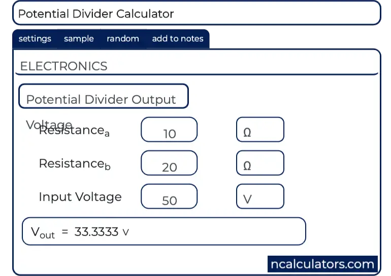
The two resistor voltage divider is one of the most common and useful circuits used by engineers. The primary purpose of this circuit is to scale down the input voltage to a lower value based on the ratio of the two resistors. This calculator helps determine the output voltage of the divider circuit given the input voltage and the resistor values. Take note that the output voltage in actual circuits might be different, since resistor tolerance and load resistance become factors.
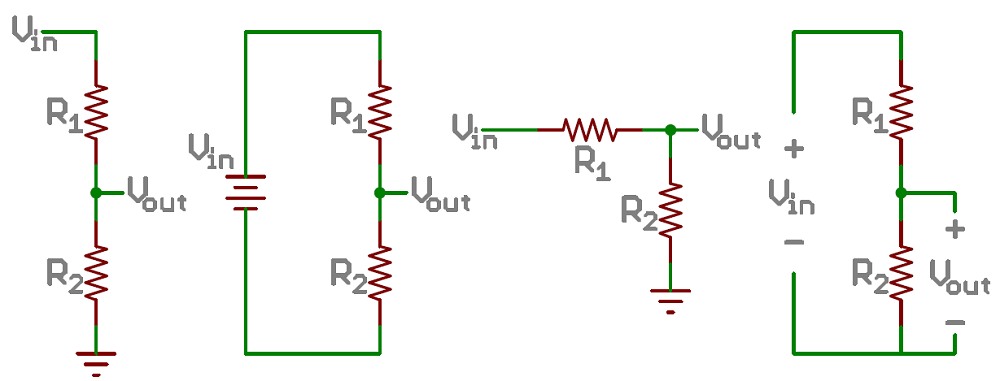
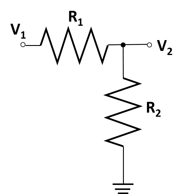
As you can see the voltage divider circuit consists of two resistors connected in series with a voltage tap between them. Use this tool to calculate the output voltage of a resistor divider circuit for a given set of resistor values and source voltage. A voltage divider is a passive linear circuit that produces an output voltage that is a fraction of its input voltage .
A voltage divider is a simple circuit which turns a large voltage into a smaller one. Using just two series resistors and an input voltage, we can create an output voltage that is a fraction of the input. Voltage dividers are one of the most fundamental circuits in electronics.

If learning Ohm's law was like being introduced to the ABC's, learning about voltage dividers would be like learning how to spell cat. A Voltage divider calculator calculates the voltage drops on each resistor load, when connected in series. Enter the total voltage supply, Resistance of first load, second load and third load and click calculate. Make use of the below simple voltage drop across resistor calculator to get the voltage drop values. Voltage dividers can be used to allow a microcontroller to measure the resistance of a sensor. The sensor is wired in series with a known resistance to form a voltage divider and a known voltage is applied across the divider.
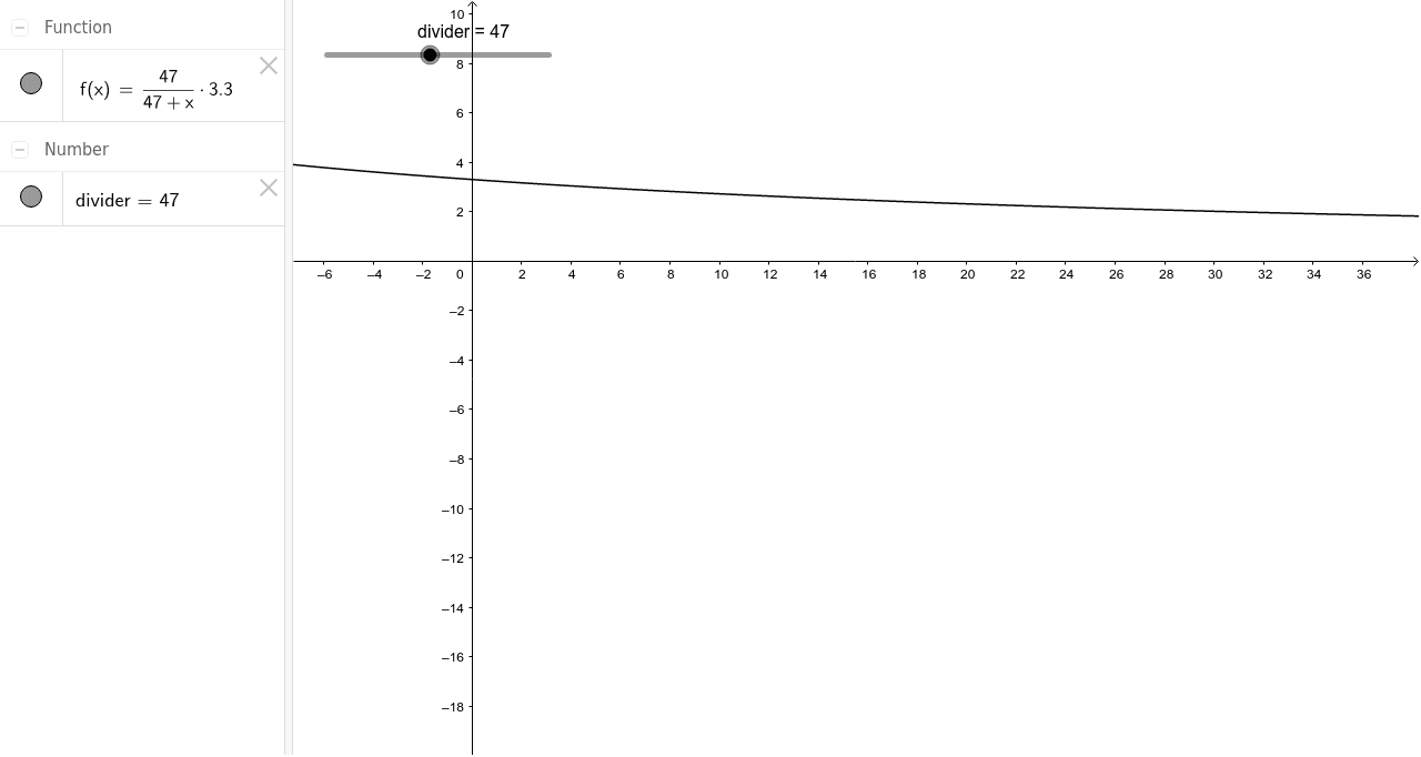
An example that is commonly used involves a potentiometer as one of the resistive elements. When the shaft of the potentiometer is rotated the resistance it produces either increases or decreases, the change in resistance corresponds to the angular change of the shaft. If coupled with a stable voltage reference, the output voltage can be fed into an analog-to-digital converter and a display can show the angle. In electronics, a voltage divider is a passive linear circuit that produces an output voltage that is a fraction of its input voltage .

Voltage division is the result of distributing the input voltage among the components of the divider. A simple example of a voltage divider is two resistors connected in series, with the input voltage applied across the resistor pair and the output voltage emerging from the connection between them. The capacitor in this voltage divider circuit produces a voltage drop. This is usually used to reduce the extremely high voltage to provide a low output voltage signal. Currently, this divider is applicable in touch screen tablets, mobiles, and display devices. Passive voltage is the basic type of divider circuit that can be made with the help of two resistors connected in series.

This circuit uses the law of the Voltage divider to measure the voltage drop across each series resistor. Voltage dividers are very common and used very often in circuits. Many times in circuits, different levels of voltage must be allocated to different parts of a circuit. To do this, a voltage divider circuit, such as that shown above, can be used. This can divide the input voltage that a circuit receives and allocate it accordingly and as needed to different parts of the circuit. However, one chip in the circuit may need 7 volts, while another chip in the circuit only needs 3 volts.
We can allocate these voltages to the different chips by a voltage divider. If we make one resistor have a value of 3KΩ and the other resistor have a value of 7KΩ, this will allocate the 10 volts into 3V and 7V. A voltage divider circuit is very simple circuit consisting of only two resistors as shown above. The required output voltage can be obtained across the resistor R2.

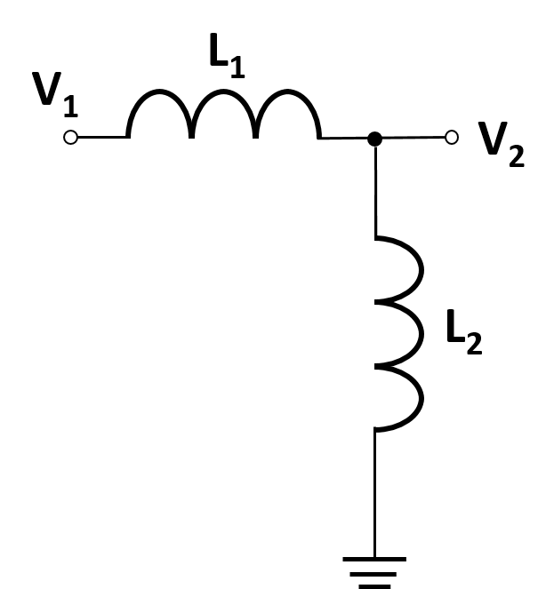
Using these two resistors we can convert an input voltage to any required output voltage, this output voltage is decided by the value of the resistance R1 and R2. A problem seen at high frequencies is that stray capacitance effects with the overall response of a resistive voltage divider. The simplest way to correct for this problem is to introduce capacitors in parallel to the resistors. Capacitor C2 which is across the output, V2, can be thought of as any stray parasitic capacitance at the output of the divider that might be part of the system.

We can see that this circuit, known as a frequency compensated divider, works like a resistive voltage divider at DC or low frequencies and like a capacitive voltage divider at high frequencies. Voltage dividers can be constructed from reactive components just as they can be constructed from resistors. Also as with resistor dividers, the divider ratio of a capacitive voltage divider is not affected by changes in the signal frequency even though the capacitor reactance is frequency dependent. A voltage divider can be used as a crude logic level shifter to interface two circuits that use different operating voltages. For example, some logic circuits operate at 5V whereas others operate at 3.3V.
Directly interfacing a 5V logic output to a 3.3V input may cause permanent damage to the 3.3V circuit. In this case, a voltage divider with an output ratio of 3.3/5 might be used to reduce the 5V signal to 3.3V, to allow the circuits to interoperate without damaging the 3.3V circuit. For this to be feasible, the 5V source impedance and 3.3V input impedance must be negligible, or they must be constant and the divider resistor values must account for their impedances.

If the input impedance is capacitive, a purely resistive divider will limit the data rate. This can be roughly overcome by adding a capacitor in series with the top resistor, to make both legs of the divider capacitive as well as resistive. The two resistor voltage divider is used often to supply a voltage different from that of an available battery or power supply. In application the output voltage depends upon the resistance of the load it drives. Where is the parallel resistance of R 2 and the load resistor R L. A potential divider circuit is a very common circuit used in electronics where an input voltage has to be converted to another voltage less than it.
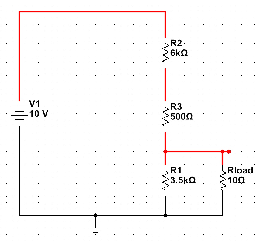
This circuit is very useful for all analog circuits where variable voltages are required, hence it is important to understand how this circuit works and how to calculate the values of Resistors. Potential divider or voltage divider circuit with external load resistor on the output The new overall resistance of the bottom resistor in the voltage divider is R2 in parallel with R3. If we call this resistor Rt, then this is easy to calculate from the fact that it is two resistors in parallel. The 4.76V is a 4.8% difference from our expected 5V output. You will need to consider if this change is critical to the circuit you are designing.
When using a higher load the divider will be more accurate and a lower load will result in an even less accurate output voltage than the one in our example. This is one of the reasons why voltage dividers should not be used for supplying power in place of components such as voltage regulators or other power supply circuits. A unity gain op amp can be used following the voltage divider in circuits that require a more precise output voltage.

The resistors in the circuit are connected in series while the voltage source is connected in this resistor. The input voltage can be transmitted between two resistors in the circuit so that the voltage is split. The Voltage Divider rule is the simplest and most important electronic circuit in any electronic circuit.
This circuit is used to convert large voltages to small voltages. In this circuit, we can measure the output voltage using only one input voltage and two series resistors. Thus the output voltage is a fraction of the input voltage.

The best example of a Voltage divider is that two resistors are connected in series. This voltage divider calculator can be used to calculate the resistive voltage drop across two, three, four or five resistors in series. The user can select the input voltage, number of resistors and the units for the resistors. A voltage divider circuit is a basic circuit that uses a pair of resistors to convert a higher voltage to a lower voltage. With 2 resistors R1 and R2, you may determine the voltage drop using our online voltage divider calculator. To use this voltage divider resistor calculator, a user must enter the value of the input voltage, VIN, the value of resistor R1, and the output voltage, VOUT, and click the 'Calculate' button.

The voltage output result will then be calculated and automatically displayed. The result of this output voltage is calculated in unit volts . A voltage divider can be used to scale down a very high voltage so that it can be measured by a volt meter. The high voltage is applied across the divider, and the divider output—which outputs a lower voltage that is within the meter's input range—is measured by the meter. High voltage resistor divider probes designed specifically for this purpose can be used to measure voltages up to 100 kV.
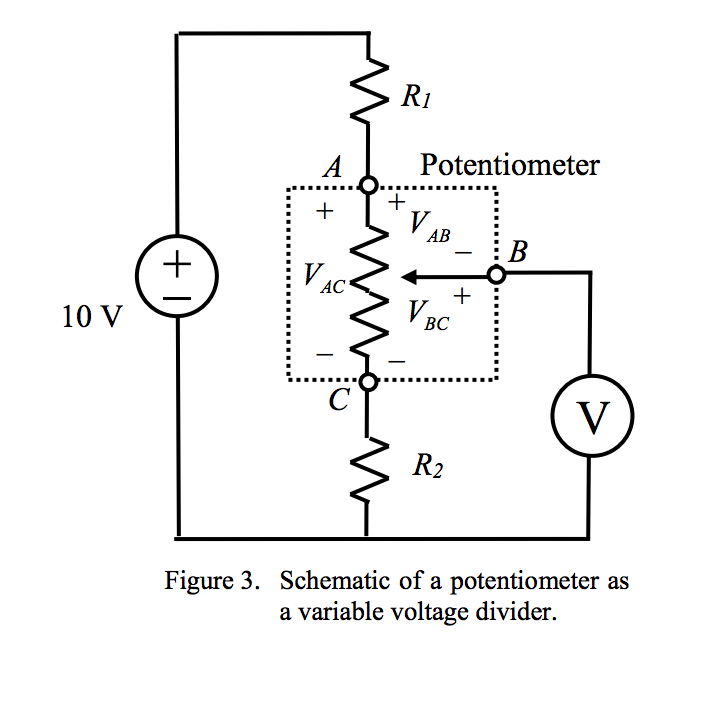
Capacitive divider probes are typically used for voltages above 100 kV, as the heat caused by power losses in resistor divider probes at such high voltages could be excessive. Potentiometer is a three-terminal resistor with a sliding contact that forms an adjustable voltage divider. The potentiometer can be used as a voltage divider to obtain a manually adjustable output voltage at the slider from a fixed input voltage applied across the two ends of the potentiometer. The voltage across Ro can be calculated by the resistances and the sourse voltage. This will create a voltage drop around the coil in the voltage divider. It consists of a coil or a single winding that receives the output voltage from any of the parts.
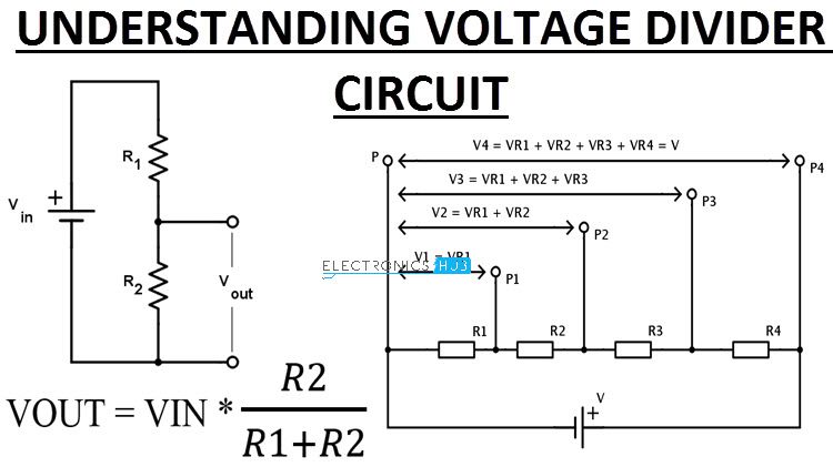
When you know the three values of the circuit above, the voltage divider that accepts the equation is the input voltage and two resistor values. Using the equation given below, we can find the output voltage. When the input voltage is applied to a pair of resistors, the output voltage will appear in the connection between them. This divider is usually used to reduce the intensity of the voltage or create a reference voltage and is used as a signal attenuator at low frequencies.

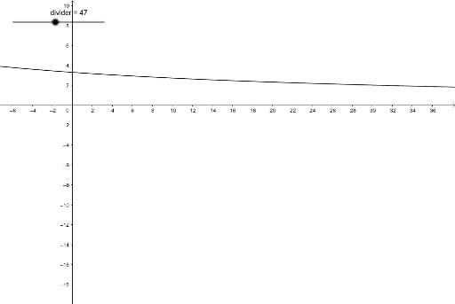
Voltage dividers may be suitable for low frequencies in DC and proportions. A voltage divider circuit is a very common circuit that takes a higher voltage and converts it to a lower one by using a pair of resistors. The formula for calculating the output voltage is based on Ohms Law and is shown below. An online calculator to calculate the output voltage, current and power of a load in dc voltage divider is presented.

Activities using the calculator to investigate the maximum power delivered to the load. Activities using the calculator to investigate the maximum power delivered to the load \( R_L \) are suggestsed. The voltage divider is a series circuit made up of two resistors that divide an electrical voltage. When the voltage divider is loaded, a further resistor is connected in parallel to the second resistor. The ratio of the partial voltages corresponds to the ratio of the resistors R1 and the resistance of the parallel connection of .

Adding a load resistor will effectively add a known fixed load in addition to the potentially-variable one. Suppose one had a 12-volt source and the intended load were 10uA +/- 5uA at 6 volts. If one just used a series resistor sized for the 10uA case , it would drop only 3V at 5uA and 9V at 15uA .
The voltage supply is applied to this circuit using a voltage source. In this circuit, we can measure the voltage drop across the resistor by applying the law of KVL and ohm. Can therefore be given as the flow of current in the circuit. The law of voltage divider is used to solve the circuit to simplify the solution. Even simple circuits can be completely solved by using this rule.
The main concept of this law is that the voltage is divided between the resistors that are connected in series in direct proportion to their resistance. The two important parts involved in a Waltge divider are the circuit and the equation. If the voltage divider operates near its extremes, with the output voltage close to either $v_$ or $0$, the percentage error will be different. To find out how much different, we repeat the analysis with the output voltage set to $90\%$ and $10\%$ of the divider range. We keep the load resistor ten times the bottom resistor, so the parallel combination of $\text R2$ and $\text R_$ is still $0.91\,\text R2$. Then connect a wire from the top of the load resistor to the center node of the voltage divider.
The interactive animation below shows a voltage divider which can be connected to a load resistance RL via the button with the red cross. Set different values for the various resistances and observe the resulting effects on voltage and current in the loaded and unloaded states. Note especially how sharply the load voltage UL drops in the loaded state compared with the unloaded state.

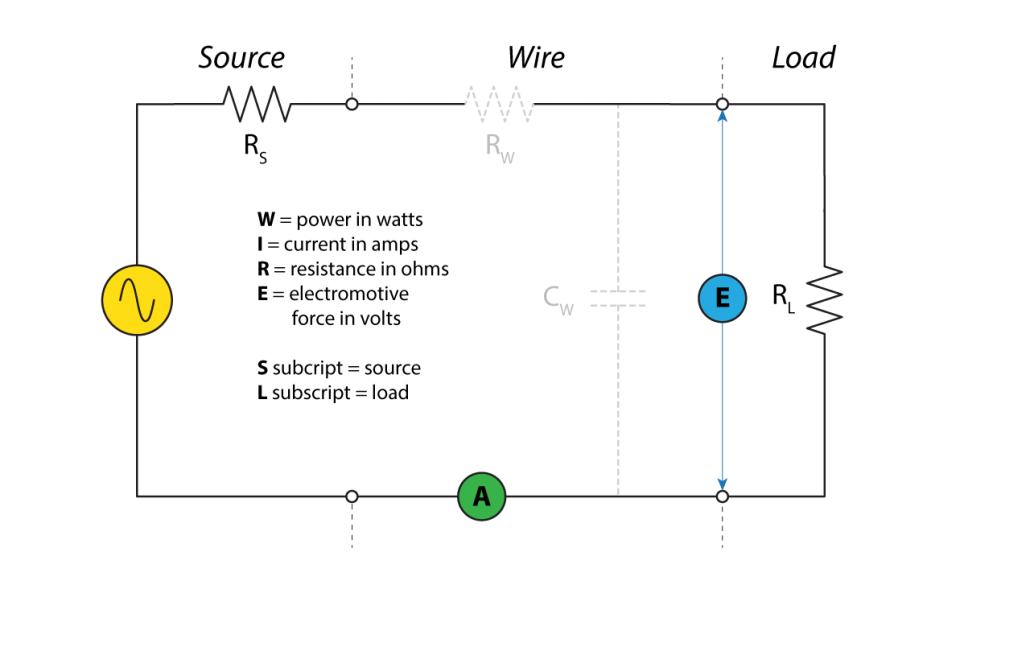
The voltage divider can be loaded by connecting it to a load . This load resistance conducts a load current IL, while resistor R2 conducts a parallel current IQ. Voltage and current division is an application of Kirchhoffs Laws. In electronics or EET, a voltage divider is a linear circuit that produces an output voltage that is a fraction of its input voltage .

The voltage and currents in the unloaded voltage divider change. To build a practical voltage divider the load requirements must be known. There is some wasted energy or bleeder current in any voltage divider circuit.